


PI-SIM ADDITIONAL BOARD FOR SIMPSONS PINBALL PARTY PINBALL (STERN)
|
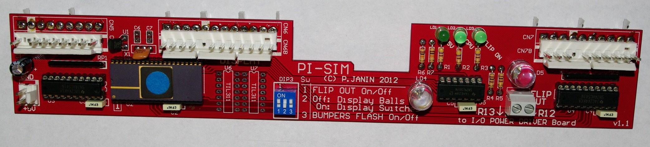
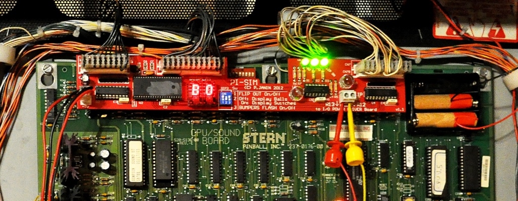
The PI-SIM board is designed for Stern's 'The Simpsons Pinball Party'. It has been built to allow the mini flipper bats of the upper playfield to be triggered when required only: when one or several balls have reached the upper playfield. |
|

|
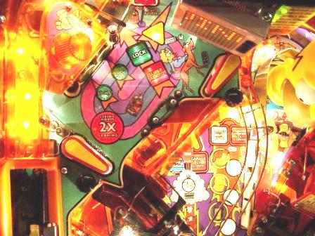
We have also added a small animation in the backbox that features two flashing LEDs facing the cooling towers when the ball hits the jet bumpers. |
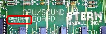
IMPORTANT NOTICE: The PI-SIM board only works with this type of CPU board: "520-5136-xx Rev. E"
Read the FAQ.
Settings
The dip switches 1 and 3, when on �ON� position, enable the PI-SIM board's new functions:DIP1. Enables the flipper bats on the upper playfield only when one or several balls are on it.
DIP3. Enables the flashing animation of the cooling towers on the backbox when a ball hits the jet bumpers.
Turn your pinball machine on, and enjoy the new functions of the PI-SIM board!
Installing the PI-SIM board
Important instructions prior to installing the board
- The pinball machine must be turned off and unplugged.
- The boards must be handled by the edges to prevent static electricity damage.
- The power cord must be in good condition and plugged to an outlet with ground before switching the pinball machine on.
- The pinball machine must be in perfect working order before installing the PI-SIM board.
- All the parts of the upper playfield must be complete, unmodified and well set up to operate properly and especially:
- the vertical kicker and its switch (VUK),
- the 3 switches of the couch,
- the mini playfield ramp switch,
- the anti-return gate of the vertical upkicker (VUK).
General assembly
Board mounting
- Slide the translite glass to remove it from the backbox.
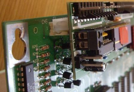
- Unplug the female CN5, CN6, CN7 connectors, lined up on top side of the original Stern CPU board.
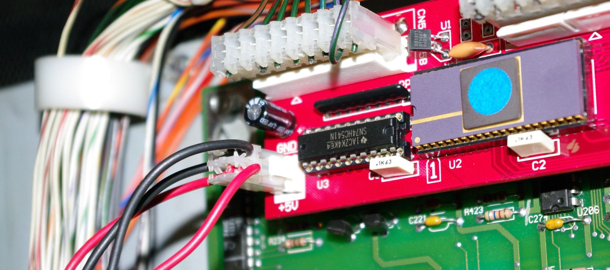
- Position the PI-SIM board in front of the (now free) CN5, CN6, CN7 male connectors of the CPU board.
- Plug it by pressing it firmly but not too strong, to snap it in place onto CN5, CN6, CN7.
CAUTION: do not press the narrower part in the center of the board, to avoid folding or breaking it. - Plug the female connectors of the pinball harnesses into CN5B, CN6B, CN7B on the PI-SIM board. Each connector has an unique pin count and a blocking key to avoid any mounting mistake.
Connecting the power supply to the PI-SIM board
- Among the backbox harnesses, find a free 2-pin female connector housing with a black wire (ground) and a red wire (5 Volts power supply).
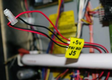
- Plug this power supply connector on the bottom left corner of the PI-SIM board (the red wire being on the lowest pin)
Connecting the flipper bats' control
Please pay attention to the next step:- On the right side of the PI-SIM board, locate the 2-pin screw-clamp connector labelled "FLIP OUT".
- Screw into it the two wire clips supplied with the board.
- Pull down the display panel to ease the access to the driver board.
- Locate R12 and R13 resistors that the two clips coming from "FLIP OUT" will clip on (exactly, on the lower part of the resistor):
Each resistor number is clearly printed in white on the upper left corner of the resistor on the driver board.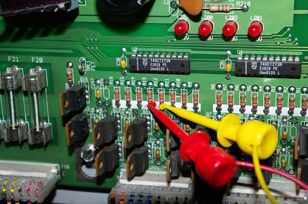
- Make sure that the dip switches #1 and #3 on PI-SIM board are on �ON� position:
Refer to the settings chapter below - Put back both the display panel and the translite glass.
Display options
For cost reasons, the PI-SIM board does not come with TIL 311 displays that provide extra information.You can install those displays on your own PI-SIM board if you wish.You just have to solder two 14-pin machine tool IC sockets on the board at locations U6 and U7, and then insert the TIL 311 displays on them (such display chips can easily be found on the web or ebay).
According to the setting of dip switch #2 you have two display configurations:
- OFF position: the number of balls on the upper playfield (B0, B1, B2, B3).
- ON position: the closed switch number on the playfield switch matrix (very convenient to repair the playfield and locate faulty switches).
Operation safety
The PI-SIM resets itself each time a new game starts. Although many tests on the board have been run and no issue has ever been reported, the flipper bats on the upper playfield may be triggered by accident during a game with no effect on the game play, since the PI-SIM board will return to normal operation upon the next game, or during the game in progress by pressing the credit button again.When entering the test modes, the flipper bats' normal operation is restored to check their working order.
Order or shipping quote: it's easy, add the board in the cart below and let us guide you. No registration needed and no account to open!
99 € (83 € excl.tax)
 Add to cart
 96 USD
Estimated value excluding French tax. Your bank or Paypal
may apply a different exchange rate.
All payments to be made in euros (€).
 131 CAD
Estimated value excluding French tax. Your bank or Paypal
may apply a different exchange rate.
All payments to be made in euros (€).
 135 AUD
Estimated value excluding French tax. Your bank or Paypal
may apply a different exchange rate.
All payments to be made in euros (€).
 72 GBP
Estimated value excluding French tax. Your bank or Paypal
may apply a different exchange rate.
All payments to be made in euros (€).
 76 CHF
Estimated value excluding French tax. Your bank or Paypal
may apply a different exchange rate.
All payments to be made in euros (€).
Estimated value excluding French tax. Your bank or Paypal
may apply a different exchange rate.
All payments to be made in euros (€).
Estimated value excluding French tax. Your bank or Paypal
may apply a different exchange rate.
All payments to be made in euros (€).
Estimated value excluding French tax. Your bank or Paypal
may apply a different exchange rate.
All payments to be made in euros (€).
Estimated value excluding French tax. Your bank or Paypal
may apply a different exchange rate.
All payments to be made in euros (€).
Estimated value excluding French tax. Your bank or Paypal
may apply a different exchange rate.
All payments to be made in euros (€).