
 | Please note that there won't be any order shipping between July 18th and August 3rd. Next shipping on August 4th. |


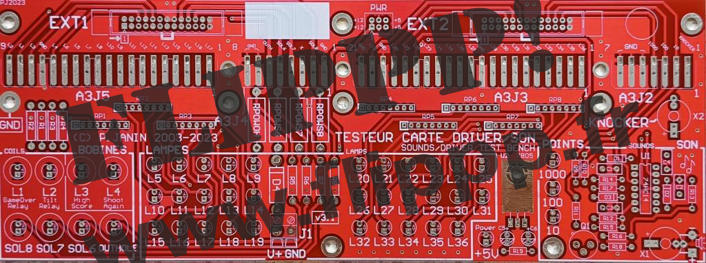
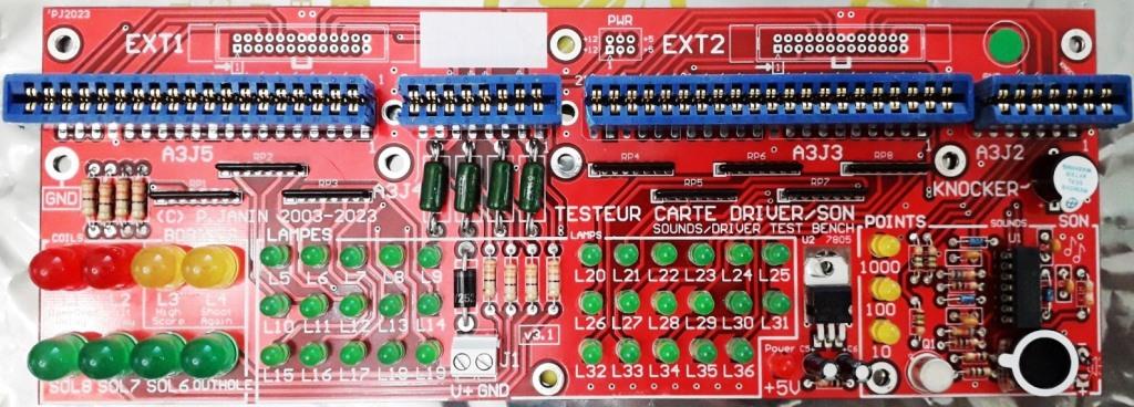
TEST BENCH PCB FOR GOTTLIEB® SYSTEM1 DRIVER BOARD
Only the bare PCB is sold here. No component is supplied. You have to assemble the test bench by following the instructions below. To get an already assembled test bench, choose this product:
DESCRIPTION
The are several areas on this test bench:- lamp outputs
- coil outputs
- sound outputs and audio amplifier
- knocker output
- 12V/5V power supply
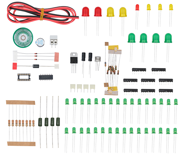
ASSEMBLING
=> Get the bill of materialA complete kit with the components (except the bare pcb and the 3.96mm connectors) is available at www.gotronic.fr
Order or shipping quote: it's easy, add the board in the cart and let us guide you. No registration needed and no account to open!
42 € (35 € excl.tax)
 Add to cart
 40 USD
Estimated value excluding French tax. Your bank or Paypal
may apply a different exchange rate.
All payments to be made in euros (€).
 57 CAD
Estimated value excluding French tax. Your bank or Paypal
may apply a different exchange rate.
All payments to be made in euros (€).
 58 AUD
Estimated value excluding French tax. Your bank or Paypal
may apply a different exchange rate.
All payments to be made in euros (€).
 30 GBP
Estimated value excluding French tax. Your bank or Paypal
may apply a different exchange rate.
All payments to be made in euros (€).
 33 CHF
Estimated value excluding French tax. Your bank or Paypal
may apply a different exchange rate.
All payments to be made in euros (€).
Estimated value excluding French tax. Your bank or Paypal
may apply a different exchange rate.
All payments to be made in euros (€).
Estimated value excluding French tax. Your bank or Paypal
may apply a different exchange rate.
All payments to be made in euros (€).
Estimated value excluding French tax. Your bank or Paypal
may apply a different exchange rate.
All payments to be made in euros (€).
Estimated value excluding French tax. Your bank or Paypal
may apply a different exchange rate.
All payments to be made in euros (€).
Estimated value excluding French tax. Your bank or Paypal
may apply a different exchange rate.
All payments to be made in euros (€).
Related products
| show 239 € (200 € excl.tax)
|
show 168 € (140 € excl.tax)
|
 show show42 € (35 € excl.tax) 
|
 show show168 € (140 € excl.tax)
|