1-Repair
2-Orders
3-Technical questions
4-Specific
Click on the questions below to toggle the answers.1-Repair
Coil issue
 The « kings » drop targets bank never resets on my Joker Poker (and also Countdown, Close Encounters, Pinball Pool, Hulk, Buck Rogers, Torch, Roller Disco ...)
-OR-
When I replace the 2A sloblo fuse under the playfield, the fuse blows immediately. what’s wrong? what can I do?
joker
poker uses a remote PNP transistor 2N5875 under the playfield, to reset
the kings drop targets bank with lamp outpout 17 (A3J5 pin 1):
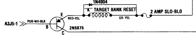
VERY
often, this transistor becomes defective and either turns the coil on
forever (blowing the fuse) or sends coil voltage upstream, blowing the
driving transistor upstream (original GTB driver or my board).
note that the fuse must be a sloblo 2A, not a fast blow. this is mandatory for continuous protection.
turn your game off, disconnect A3J5, then check that transistor under the playfield following my instructions here:
https://www.flippp.com/faq/F107
it is most likely dead.
if dead, replace it by a similar transistor (acceptable ones are listed in my FAQ here: https://www.flippp.com/faq/F118)
then keep A3J5 disconnected and turn game off.
the coil should not be energized and the fuse won't blow.
turn game off, connect A3J5, turn game on, see if the coil is not energized. (which should be the case)
then go to TEST COIL menu and try all coils.
My PI-POP80 does not work: it either does nothing or blows the fuse in serial with the coil. What to check first?
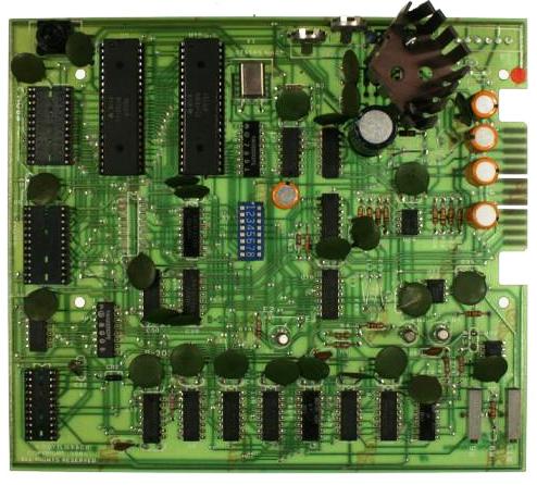
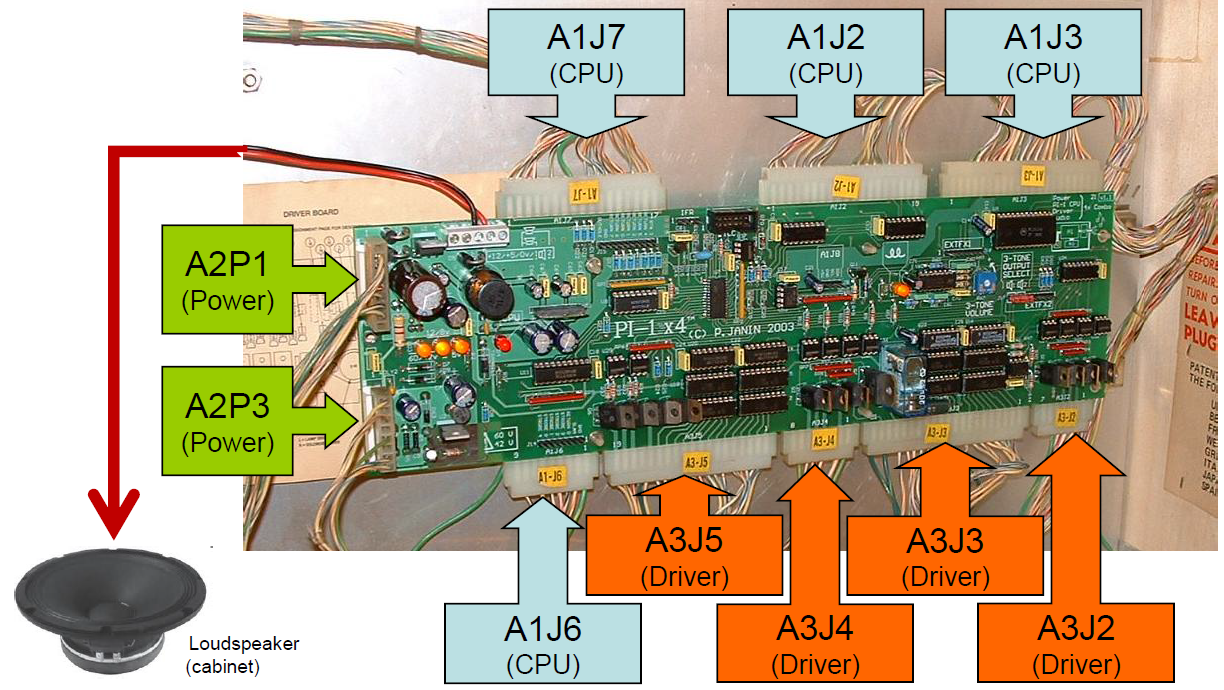
A pop bumper driver board (codenamed: PBDB by Gottlieb) needs 5 different signals to work, as per the picture below:

The +5V comes from connector A1J6 pin 18. This pin feeds +5V to all pop bumper driver boards.
A good +5V +/- 5% is mandatory, but won’t do the job alone.
BOTH grounds should be connected, but not together to the CPU:
- The power ground runs straight from the common grounds copper rail in the cabinet.
- The signal ground runs from CPUA1J6, along with +5V.
Do NOT cross-connect them on the pop bumper driver board itself!
my flippers are not working, even though the board (PI-1, PI-1 X4, PI-80) starts up correctly and reports no errors
it does not depend on my board: like all games from those years, the flippers are driven directly by the buttons.
the voltage going to the flippers goes through the game over (Q) and tilt (T) relays under the playfield.
the exact wiring is detailed in the game’s original manual, which you absolutely need to have on hand.
several possible causes for the same failure:
- the game over (Q) and tilt (T) relays are not activated; normally they should click once together at startup
- contacts on these relays are bent or dirty, preventing the coil voltage from reaching the flipper buttons
- the end of stroke (EOS) switches on the flippers are worn, bent, or dirty; in that case the small coil (each flipper has 2 coils wound on the same core) stays energized all the time, making it look like the flippers are not working
- the general +24V coil supply is missing upstream of the relays, due to a blown diode bridge or dedicated fuse.
Display issue
ALL my displays are off, or went off during a game. what should I do?
the displays are powered by the 60V power supply which is protected by a little cylindric fuse (brown or black) on a socket, just right of the A2P3 (PI-1 X4 board) or A2J3 (PI-80 board) connector.
if the fuse has blown, it's because one of the displays has become defective.
the board itself is not at fault, but at least 1 of the displays draws more current than it should and makes the fuse blow.
with time, there is a risk to damage the power supply section of the board.
depending on the delivery time, a replacement fuse was delivered with each board (in a little zipped bag).
but we need to find the culprit display before replacing it!
start with the following procedure:
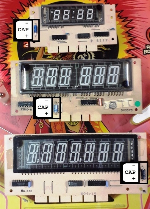
turn the game OFF, disconnect connector A2P3 (PI-1 X4 board) or A2J3 (PI-80 board), A1J2 and A1J3 from the CPU, and disconnect the edge connector on ALL the displays.
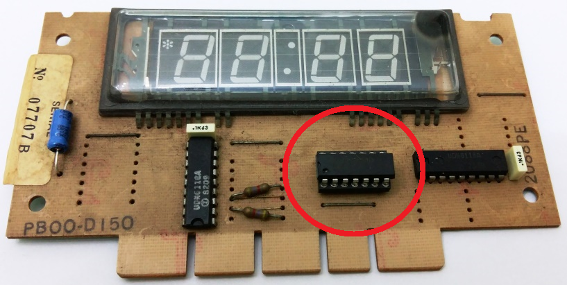
then, on each display (one at a time) with your multimeter on "2000 ohms" setting, measure the resistance across the 1uf 100V electrolytic capacitor (small orange or silver container), as shown on this picture :
- if the measured resistance is higher than 2000 ohms : the display is PROBABLY good, but it is not an exhaustive test
- if it is lower, one of the UDN6118 chips is likely to be damaged.
write down the value measured on each display of the game, then cross-compare them: if one of the values is significatively lower than the others, this is probably the faulty display.
additional test:
reconnect A2P3 (PI-1 X4 board) or A2J3 (PI-80 board), A1J2 and A1J3 from the CPU (with the game still OFF), replace the fuse (depending on the date of delivery, a spare one might be provided in a separate zip bag).
then only plug ONE DISPLAY AT A TIME, turn the game on, check whether the 60V is still good (60V/42VLED is lit) :
- if yes, the display is probably good. turn the game off, disconnect the display that you just tested, connect the next display, and continue.
- if no, the defective display is the one connected last.
on the suspected defective display, desolder one of the two UDN6118 chips and redo the 2000 ohms resistor measurement on the display: if the value is now closer to the other ones, this chip was at fault, otherwise it's the second one.
alas, none of these 2 tests is exhaustive, we may not be able to draw any conclusion.
if you got no electronics skills, it will be difficult to identify the faulty display because the current drawn thru the +60V to the displays must be measured.
in that case, I strongly advise to get in touch with a skilled repair person or company and send them the displays for test and repair.
IMPORTANT: ALWAYS turn the game OFF before plugging/unplugging any connector, otherwise it would cause further damage to the game!
one of my displays shows very bright digits
it comes generally from a bad contact on the display connector.
try to shake gently the cables coming to the connector.
if the very bright digits disappear, the problem is confirmed, so inspect the edge connector
else either the connector is badly damaged, or the display itself has a problem.
IMPORTANT: turn off the pinball before unplugging any display or more damages will occur.
some of my displays are not working properly: missing segments or digits
if the problem shows only on one of the displays, you have to check the
display itself (faulty display, dirty edge connector, cut wire ..)
swap it with a known working one to see if the problem "moves":
- if it moved, then the display itself is faulty
- if it didn't, then there is a connection problem (dirty edge connector, cut wire).
if TWO displays show the same problem it may come from the main board or a bad A1J2/A1J3 connector:
** on PI-1 and PI-1 X4 boards:from connector A1J2:
- SEGMENTS a..h of displays 1 and 2 and credit display are driven together
- SEGMENTS a..h of displays 3 and 4 are driven together
from connector A1J3:
- DIGITS of displays 1 and 3 and credit display are driven together
- DIGITS of displays 2 and 4 are driven together
** on PI-80 board (most of the games):from connector A1J2:
- SEGMENTS a..h of displays 1 and 2 are driven together
- SEGMENTS a..h of the credit display are driven separately
- SEGMENTS a..h of the displays 3 and 4 are driven togetherfrom connector A1J3:
- DIGITS of displays 1 and 3 and credit display are driven together
- DIGITS of displays 2 and 4 are driven together
swap the faulty pair of displays which the pair of working ones to see if the problem "moves":
- if it moved, the problem is linked to the display itself
- if it didn't, then there is a connection problem (dirty edge connector, cut wire).
on PI-1 and PI-1 X4 boards, the little display is linked to displays 1 and 3.
Does it work properly?
if it does, the PI-1 X4 board is good, displays 1 and 3 are the culprits.
if it doesn't, either the PI-1 X4 board is damaged or it is disturbed by displays 1 and 3
IMPORTANT: always turn the game OFF before plugging/unplugging any
connector, otherwise it will cause further damage to the game!
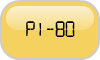
Some of my displays read blank and some read 1's (PI-80)
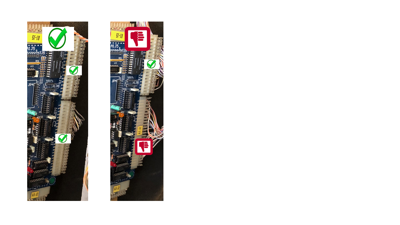
before suspecting the PI-80 board, the power supply or the displays, are connectors A1J2 and A1J3 correctly plugged in?
as
marked on the board, they must be plugged in reverse position, A1J2 on
the bottom, A1J3 on the top, name sticker toward the back of the front
head
Lamp issue
Some lamp(s) always off, always on or dimly lit
LAMP TROUBLES -- PI-1 X4
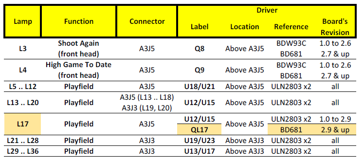
LAMP TROUBLES -- PI-80
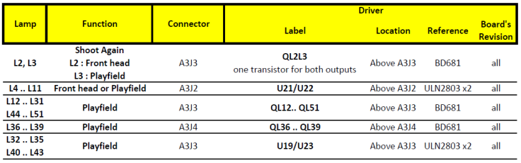
Lamps driven by a pair of ULN2803 circuits
Lamps always on or dimly lit:
turn the pinball game off, remove one
of the 2 integrated chips (no matter which one) then turn the game on: if the
faulty lamps are now off, that chip is faulty and must be replaced.
otherwise (lamps still lit), replace the 2nd chip.
Lamps always off:
both integrated chips must have been damaged, and must be replaced at the same time.
Some or all the lamps in the backbox that light the backglass are off. Are my boards faulty?
These are General Illumination lamps, they aren't controlled by the boards (only by the TILT relay) and have a dedicated fuse.
If none of them is lit, check the fuse near the transformer and the diode bridges.
If some are lit and some aren't, it means that the fuse is OK, but then :
- the sockets may be rusted or tarnished
- some lamps may be dead
- the metallic wires behind the sockets may be cut somewhere.
Power-on issue
the pinball lights on, the power-on sequence displays an error message, it is impossible to start a play : when I press the CREDIT button, the TILT relay clicks twice, the displays show « TEST » and the play does not start
The error comes from one or several faulty coils or their diode in parallel or their associated fuse or the associated contacts.
The board detects the error, warns the user about it, and prevents from starting a play to avoid aggravating the problems.
A full description of all error messages and their possible
causes & fixes can be found in the PI-1/X4 and PI-80 boards manuals.
In a first step, narrow the failure search by following the simple steps below:
PI-1 and PI-1 X4 :
- CHECK + name of the coil + STUCK SWITCH:
After activating a coil, one of its associated switches is permanently closed.
It's typically the case of a broken drop target that doesn't reset, or an eject hole switch always closed.
Follow this procedure: « IN CASE OF PERMANENTLY CLOSED SWITCH ».
PI-1 X4 specifically:
- CHECK + name of the coil + CANNOT DRIVE:
Impossibility to activate a coil (eg. dead fuse or dead driving transistor).
Follow this procedure « IN CASE OF A COIL WHICH CAN'T BE ACTIVATED ».
- CHECK + name of the coil + LOCKED ON:
Coil permanently activated (eg. driving transistor in short circuit).
Follow this procedure « IN CASE OF PERMANENTLY ACTIVATED COIL ».
PI-80 specifically:
- ERROR 1 or 3 :
Permanently activated coil (eg. driving transistor in short circuit).
Follow this procedure « IN CASE OF PERMANENTLY ACTIVATED COIL ».
- ERROR 2 :
Impossibility to activate a coil (eg. dead fuse or dead driving transistor).
Follow this procedure « IN CASE OF A COIL WHICH CAN'T BE ACTIVATED ».
- ERROR 4 :
After activating a coil, one of its associated switch stays permanently stuck.
It's typically the case of a broken drop target that doesn't reset, or an eject hole switch always closed.
Follow this procedure: « IN CASE OF PERMANENTLY CLOSED SWITCH ».
IN CASE OF PERMANENTLY CLOSED SWITCH:
Check all the switches behind the drop-targets, the eject hole switches ...
The contacts may be dirty or the contact blades too close from each other.
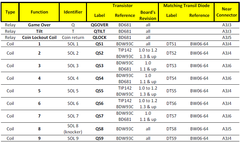
IN CASE OF PERMANENTLY ACTIVATED COIL:
For a PI-1/X4 :
Turn pinball OFF, unplug connectors A3J2 and A3J4, then turn pinball ON: the error should have disappeared.
If the error is still there: pinball OFF, plug A3J2 only,
turn ON: if the error is still there, there is a problem on the «
knocker » coil or on transistor Q1.
If the error has gone: pinball OFF, plug A3J4 only (unplug A3J2), turn ON: if the error is still there, there is a problem on 6 7 8 or « outhole » coil.
For a PI-80 :
Turn pinball OFF, unplug connectors A3J4 and A3J5, then turn pinball ON: the error should have disappeared. Pinball OFF, plug A3J4 only, turn ON. If the error is still there, there is a problem on one of the 1 2 5 6 9
coils or on their respective driving transistors QS1 QS2 QS5 QS6 QS9.
Pinball OFF, plug A3J5 only (unplug A3J4), turn ON. If the error is still there, there is a problem on coil 8 « knocker » or on
transistor QS8.
Once the faulty coil driver is found, you must control the associated coil(s) + their diode(s) on the playfield.
Follow the procedure « CHECKING DIODES AND COILS ».
IN CASE OF A COIL WHICH CAN'T BE ACTIVATED:
For all the boards:
Find in the game manual the fuse type which is in series with the coil it protects (if present, depends on the game).
Check the fuse, check if blown or not, and replace it by the right type then check the coil and its diode before turning the game on.
CHECKING DIODES AND COILS:
Checking diodes is very easy: unsolder one of its 2 legs (else the coil in parallel will result in a false measure) and test the coil then the diode with a DMM. Position "200
ohms" for the coil, or position "diode" for the diode: red wire on the non-banded side, black wire on the banded side (white ring).
Tip: cut one of the diode legs in the middle, easy to restore with a solder joint.
Compare the coil resistance with the Gottlieb coil chart in your manual.
Contact us if needed.
Selecting the game, language, entering the menus ... is either impossible or very random
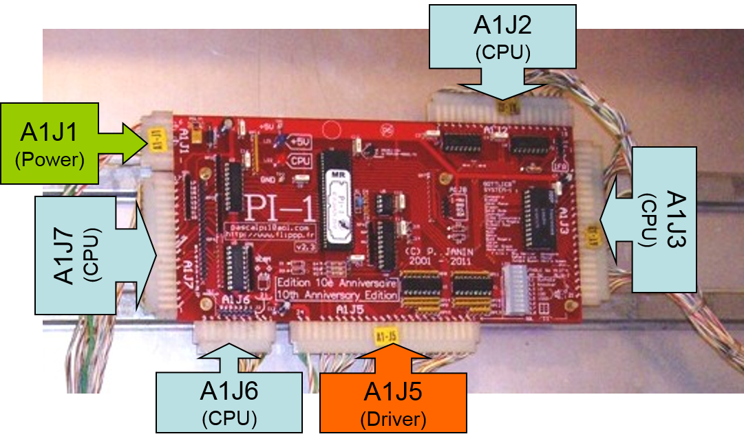
The most common problem for menus and game/language selection is the connector A1J6 (on PI-1 or PI-1 X4 boards) or A1J5 (on PI-80 board) which is often corroded due to the former leaking battery and prevents TEST and CREDIT buttons to work as they should.
Did you inspect it carefully?
If
a few pins need to be replaced, I usually replace them one by one,
otherwise I replace the whole connector by a JAMMA connector which I
trim to the desired length. They are extremely robust.
One thing you can try before replacing any connector is to disconnect A1J7 (on PI-1 or PI-1 X4 boards) or A1J6 (on PI-80 board) and see whether it works better. There may be problems on the switches matrix under the playfield that interact with the switches behind the coin door.
Sound issue
Switch issue
the game in progress ends abruptly and a "STUCK SWITCH xx" message is displayed. what's wrong?
this warning message says that the switch number "xx", pertaining to one
of the pop bumpers on the playfield, remains closed permanently.
this message may be turned off by means of COMMON SETTING 28
"CHECK BUMPER" but I don't recommend it, because the rootcause for that
closed switch must be found.
it may be an electrical or mechanical problem.
the cup switch of each pop bumper must be checked to find the stuck one.
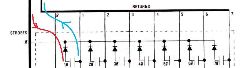
How does the switch matrix work? what are STROBE and RETURN signals?
all boards (PI-1, PI-1 X4, PI-80) work the same.
basically,
the CPU board sends out strobe signals (=rows) and they intersect with
return signals (=columns) that go back to the CPU.
at each intersection, you got a switch (=contact) and a diode in serial with it.
on
the following drawing, when the switch #10 is closed, the active-low
strobe signal (in RED, one active strobe at a time) is fed to the
playfield switch thru the diode.
when the switch is closed, this signal goes back to the return input signal (in BLUE) of the CPU.
the CPU detects it and knows that this given contact number #10 has been closed.
checking the diodes is pretty easy.
disconnect the connectors:
- A1J6 and A1J7 for PI-1 and PI-1 X4 boards
- A1J5 and A1J6 for PI-80 boards
then
measure each diode on "diode" setting with red DMM plug on NON BANDED
side and black DMM plug on BANDED side: it should read between 0.2 and
0.3V.
if a faulty diode must be replaced, information about replacement diodes can be found here:
https://www.flippp.com/faq/F49
2-Orders
Guarantee
Hand delivery at a show
Intellectual rights
Before ordering I need to know about the legalities of using the Gottlieb name/intellectual rights
name: I use it sparingly in my manuals will full credit given to the rightsowner.
boards: I redesigned everything from scratch, both hardware and software.
I don't reuse the original roms and game proms unlike other repro boards around.
The various boards presented on this web site, although carefully
designed to work in Gottlieb® System-1, 80 and 80A games series, are not
built under licensed Gottlieb® manufacture.
Placing an order
I sent several support messages but still no answer after several hours. As a customer I was expecting a much faster reply!
Do NOT send the same message several times in a row!!
It will be processed as soon as possible, usually within 24 hours
except under some circumstances (such as holidays) clearly stated on top
of the web site.
I have designed, manufactured and programmed these boards as part of my pinball hobby, and not as a business.
I make no profit from these endeavours.
I am more than happy to help people who buy my boards, and I
appreciate the feedback from them, especially where it helps to improve
the boards.
I do have a real job though, and a big family, and I am not able to
provide continuous and/or immediate help on a 24/7 basis.
I hope that you can appreciate this..
If not and you are not satisfied with what I provide, then return
the board to me in original condition and I will refund the cost of the
board you have purchased from me (except shipping fees).
No restocking fee will be charged if the board is returned in new condition in its original, unopened antistatic bag.
VAT
3-Technical questions
Available games
Before installing a new board
Must the game be fully operational before installing the new board?
It is an ambiguous question: a non-working game is one of the main
reasons that people purchase my boards! In the manual as
well as on top of the quick installation leaflet, I remind users of
the most important points to check PRIOR to any installation. It is
ALWAYS
dangerous to install a new board without performing some basic
checks
on the game! All my boards embed advanced hardware and software
protections against all kinds of failures which would damage the
original Gottlieb boards, but it is always wise to check for shorted
coils & lamps sockets, damaged displays, blown fuses, broken
connector pins, dead diode bridges etc...
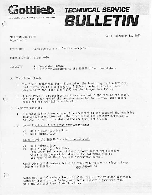
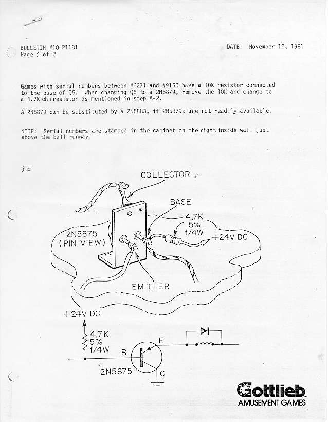
my machine does not have the pull-up resistors added to the under playfield mounted PNP transistors. should I do that before I install your board?
the pullup resistors are indeed recommended by GTB (as shown on the attached technical bulletins).
I
also highly recommend them, and not only on black hole but on ALL games
that have PNP transistors under the playfield, including system-1
games: joker poker, countdown, close encounters, pinball pool, hulk,
buck rogers, torch, roller disco, asteroid annie.
the problem
lies more on the PNP transistors they used under the playfield than the
driving transistors upstream (GTB driver or my board).
due to their
high current gain, they may remain slightly energized instead of being
completely turned off, leading to overheating and possible coil meltdown
after some time.
TIP: the original PNP transistors may not be available anymore, you can freely use one of these instead:
2N5875
2N5879
2N5884
BDX18
BDX64
BDX66
MJ2500
MJ2955
Chimes
Coin slots
Components
how to test transistors?
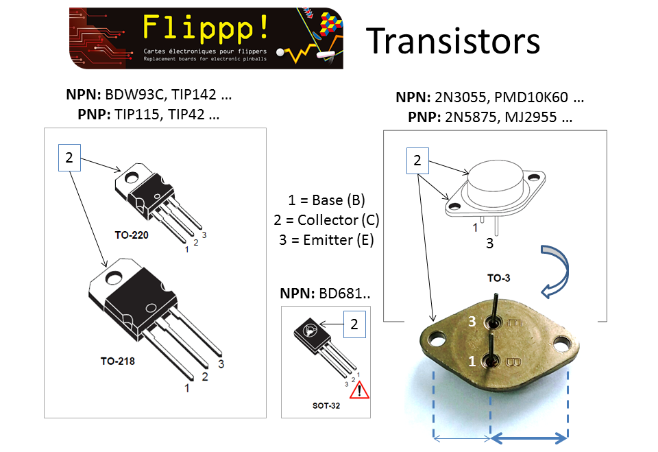
NPN
to measure a NPN transistor (on the schematics, the arrow runs from base to emitter) :
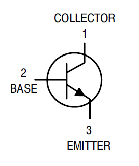
examples: BDW93C, TIP122, BC547, 2N3055, BD241, TIP31, MPSA13, MPSU45, 2N6043..
Set your DMM on "diode" setting
- red tip on B, black tip on E : readout 0.5 to 0.7V OK (MPSA13 or MPSU45: 1.2V to 1.4V OK)
- red tip on B, black tip on C : readout 0.5 to 0.7V OK
- red tip on C, black tip on E : readout "1 " or "OL" (open circuit) OK for most, but some may return 0.5 to 0.7V (depends on the transistor’s internal structure) which is OK too
Any short-circuit readout like “0” or “000” means that the transistor is dead shorted.
PNP
to measure a PNP transistor (on the schematics, the arrow runs from emitter to base) :
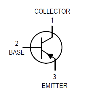
examples: 2N5875, 2N5879, 2N5884, TIP2955, MJE2955, BC327..
Set your DMM on "diode" setting
- red tip on E, black tip on B : readout 0.5 to 0.7V OK
- red tip on C, black tip on B : readout 0.5 to 0.7V OK
- red tip on E, black tip on C : readout "1 " or "OL" (open circuit) OK
for most, but some may return 0.5 to 0.7V (depends on the transistor’s
internal structure) which is OK too
Any short-circuit readout like “0” or “000” means that the transistor is dead shorted.
Personal
tip: connect your DMM probe tips together (and to nothing else), so you
know how the “shorted” condition is displayed on your DMM. Not all DMMs display it the same way.
Under the playfield PNP transistor replacements
TIP115 : only used under the playfield of Buck Rogers and Torch. BDX66C and its equivalents (2N5875, 2N5879, 2N5884, BDX18, BDX64, BDX88, MJ2500, MJ2955) are used under all System1, System80, System80A, System80B playfields except Buck Rogers and Torch.
All these transistors can be ordered here:
spare components.
Not all replacement components are available for sale on line. Why?
some are not
readily available on line because they address the kind of repair that I don't normally let people make themselves.
I
have seen too many boards damaged/ruined by self-appointed repair
persons that don't know how to identify/solder/desolder components.
so when special demands show up, I prefer to treat them on a person-to-person basis.
Testing diodes
COIL DIODESdesolder one of its 2 lugs then measure the coil THEN the diode with a DMM ("200 ohms"
range for the coil, "diode" for the diode: red tip on the non banded side, black tip on the banded side (white ring)). The coil diode measures are between 0.6 and 0.7V.Personal tip: I cut the lug right in the middle so it's easy to repair with a small drop of solder afterwards.Only use 1N4004 or 1N4007 diodes.
DIODE BRIDGES
The diode bridges are 4 basically 4 diodes in a package. With the pinball schematics on hand, take 4 measures (1 for each diode). No need to desolder the bridge, just remove the fuse downstream.
Beware: if a "boost" capacitor has been soldered in parallel on the « + » and « - » outputs of the coil diode bridge, the diode measurement may be inaccurate.
SWITCH MATRIX DIODESTo check the playfield diodes, don't desolder anything, just unplug A1J5 and A1J6 (PI-80 board) or A1J6 and A1J7 (PI-1 or PI-1/X4 board) and measure the diode with a DMM (see 1st paragraph) . The playfield diode measurement is between 0.2V and 0.3V (switch matrix).Never use 1N4148 diodes! See
https://www.flippp.fr/faq/F49 for acceptable replacement types
Connectors
Displays
Do the PI-1, PI-1 X4 and PI-80 boards drive the new replacement LED displays from Boston Pinball Company and Wolffpac?
absolutely:
Boston Pinball displays: https://www.bostonpinballcompany.com/displays.htm
I have been personally using them for years in some of my games delivered ready to install, simple set-up, adjustable brightness (dimmer), 4 6 or 7 digits, various colors available, excellent rendering
Wolffpac displays: https://www.wolffpactech.com
I never had a chance to try some myself yet, but two close friends did and were very satisfied
warning: come as a kit = you must SOLDER them yourself, very simple set-up, 6-digit cyan only (as of April 2021), very good rendering
Sidenote: some earlier board revisions may require a minor modification, simply ask me directly for details.
Replace 6-digit displays by 7-digit displays (PI-80 board in system-80 mode)

7-digit scoring setup on my PI-80 board is much easier than on an
original Gottlieb CPU, because all the software programming is already
embedded and readily available for ALL system80 games.
download the board's manual and proceed to page 4 COMMON SETTING: setting 30 "7-DIGIT MODE" will turn it on/off.
no need to fumble with tweaked game proms and roms as on Gottlieb CPU board!
however, you still need to make the 7-digit displays fit your game's existing 6-digit wiring.
two options:
1) use original Gottlieb 7-digit vacuum displays AND re-wire all display connectors.
this has been described elsewhere on the web.
it's long, tedious, and prone to errors.
2) get specific 7-digit LED displays from Boston Pinball:
https://www.bostonpinballcompany.com/displays-S80A.htm
they
make 7-digit displays that are both 7-digit and 6-digit pinout
compatible (a chip must be flipped on the displays), as shown here: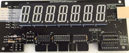
some additional wires must be connected across the displays themselves, but it's very easy.
then there is no need to change the wiring at all!
enjoy the 7-digit displays then: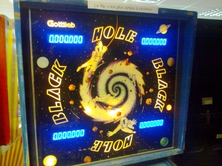
High scores
Lamps
Manuals
Original Boards / Manuals / Memories
Should I get new eproms and/or use the original proms?
No need to: all supported games are built in the main processor.
Selection is made by menus upon power-up or by dipswitches (sound
boards). No original prom is needed anymore.
The sound/speech replacement board is the only exception. It needs the original sound proms.
As they are copyrighted by Gottlieb Development LLC, I don't sell them.
You need to get them thru authorized resellers (read the following FAQ).
What does the small A24 board, located above the original CPU board, do? What should I do of it if I install a PI-80 replacement board in my game?
the A24 reset circuit board monitors the displays activity on the CPU board.
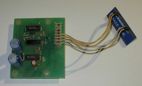
It resets the CPU in case of display freeze for a given time = a
sign that the CPU board has hung (such as after a coil problem).
In arcade rooms, that prevents the CPU from remaining locked up for an extended time, especially in a coil-burn state.
At home, this reset board has little or no use, as the game does not remain powered for long continuous periods.
The PI-80 replacement board embeds similar & improved hardware
that makes this reset board useless. Moreover, it cannot be connected to
the PI-80 board.
Reliability
No reliability problems over time?
Not at all, except typical mistakes such as coils (= shorted coils or without a diode) not checked by the user
prior to installing my board
which may cause driver transistors blow; as would be the
case on ANY other electronic board. Worse, the original CPU boards would
also be badly damaged, which is not the case on my board. The damage,
in 99.99% of the cases, is limited to a transistor.
Settings
Optional disabling of “SLAM” switches
The so-called « SLAM » is the feature that immediately puts an end to the game in play when for
example the coin door is banged, or when the game was lifted up too high to bring a lost ball back into
play:
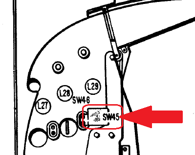
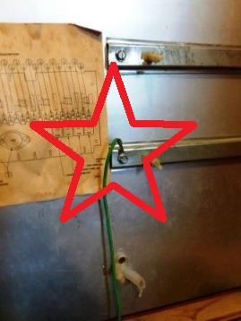
1. The kick in the coin door is detected by a classical switch, normally closed, with a tiny weight
on its tip, located on the inside of the door. Following a too strong kick, the weight opens the
switch and triggers the ‘SLAM’.
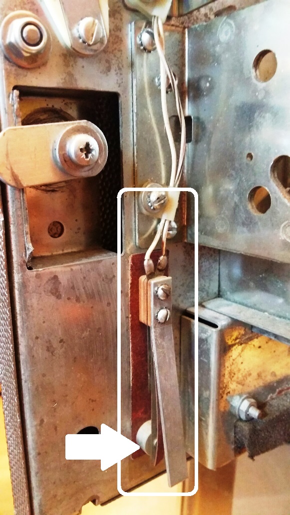
(box : the complete mechanism - arrow : where the contact is made, normally closed)
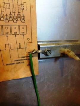
2. The excess game lift is detected by the ball on its captive rail, located on the left side of the
cabinet, near the ‘TILT’ pendulum. If the game is lifted too high, the ball rolls over the end of
course switch which opens and also triggers the ‘SLAM’.
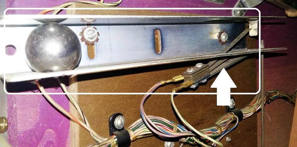
(box : the complete mechanism - arrow : where the contact is made, normally closed)
Therefore, in order to allow the game to run, it is very important that the two above contacts are duly
closed. Very often, the switch blades are dirty or too wide open, preventing the game from starting.
For normal home usage, the 'SLAM' feature can be disabled. A clothes peg is enough to keep the
contacts well closed, but it can also be done on the board: - on the PI-1 board: insert a jumper between the 2 rightmost pins of J2 row just above A1J6
- on the PI-1 X4 board: insert a jumper between the 2 rightmost pins of J14 row just above A1J6
- on the PI-80 board: thanks to the setting #24 of COMMON SETTINGS menu.
Software updates
Sound boards
Do I need an additional sound board or it is embedded into the PI-80 board?
You must keep your existing sound
board for the present time, until I release my own sound add-on
board. If the sound board of your pinball game (refer to the list of
available games on the 'Boards' page) does not work, you can replace
it by my stand-alone PI-FX sound board. It plugs into the existing
sound board connector in the front head and requires no modification
to the game whatsoever.
4-Specific
The upkicker coil does not work. All the coils and fuses are good. what’s wrong?
this is a common mistake that Haunted House owners make, because the information was never "widely spread" by Gottlieb.
HH playfield was manufactured in two versions: normal production run (the most common) and preseries (“sample games”).
they are compatible EXCEPT for the upkicker coil:
- the production games use SOL2 to drive that coil
- the preseries games use lamp 14 output + PNP transistor 2N5875 under the playfield to drive that coil
refer to the Gottlieb service bulletin:


get
the full PI-80 manual from my web site and go to the specific page for your
game: you must select the correct game configuration in the GAME SETTING
menu.
I would like to add speech to my Haunted House while keeping it in single ball mode, how to do that?
There are 2 separate projects around this game :
1. The Haunted House in
multiball with speech project comes from a fruitful co-working with the Davroux brothers who added our specific sentences to the existing sounds.
This project only works with our PI-80 board.
It needs a PI-80 board + an original GTB sound/speech board with
the specific sound proms, to be acquired directly from the Davroux
brothers
2. The Haunted House with speech version (hence single ball)
reuses the original CPU to which the Davroux brothers added code to
trigger additional sentences
This version work with the original GTB boards ; the PI-80 board
software has not be fitted for this yet, due to lack of time and demand
It needs an original GTB CPU board + an original GTB sound/speech
board ; both boards require specific game and sound proms, different
from the multiball version above, to be acquired directly from the
Davroux brothers


Is there any way to adapt your PI-SIM board for a TSPP board 520-5300 Rev A?
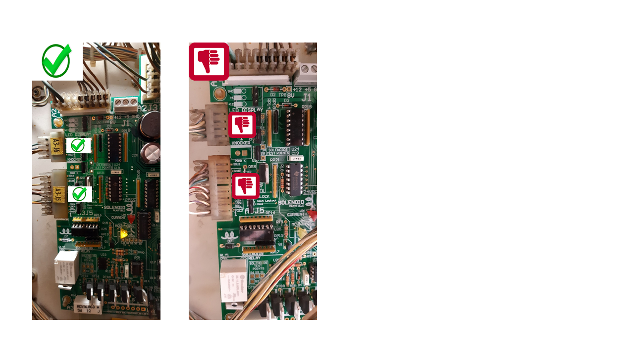
there are actually 3 CPU revisions for this game:
http://www.pinwiki.com/wiki/index.php?title=Sega/Stern_White_Star_Repair
refer to chapter "3.1.1 CPU / Sound Board" :
- top right : 520-5136-16 Rev. E (Monopoly) => the one we currently have in our TSPP test game
- top left : 520-5136-16 Rev. D => same one with additional logo "SEGA" instead of "STERN"
- bottom center : 520-5300-00 Rev. A (Lord of the Rings) => the newest of all 3 which causes trouble with CN5 farther from CN6
for some reason we don’t know, Stern guys redesigned their CPU and slightly shifted the top left connector.
on this picture, you will understand why my board does not fit on a rev. A :
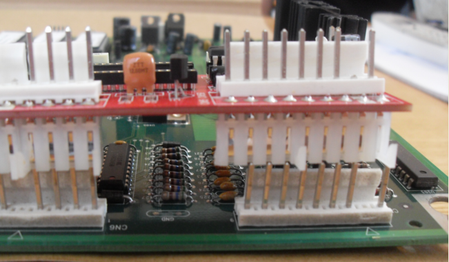
my PI-SIM board plugs into CPU 520-5136-16 Rev. E, and NOT on CPU 520-5300-00 Rev. A.
we studied the cost to make a specific model for that CPUs.
but a limited PCB batch would cost a fortune, and we don't have this CPU for trials.
a possible mod would be simple though: build "connectors extenders" for CN5 CN6 and CN7, and bend them apart to fit that CPU's specific connectors spacing.


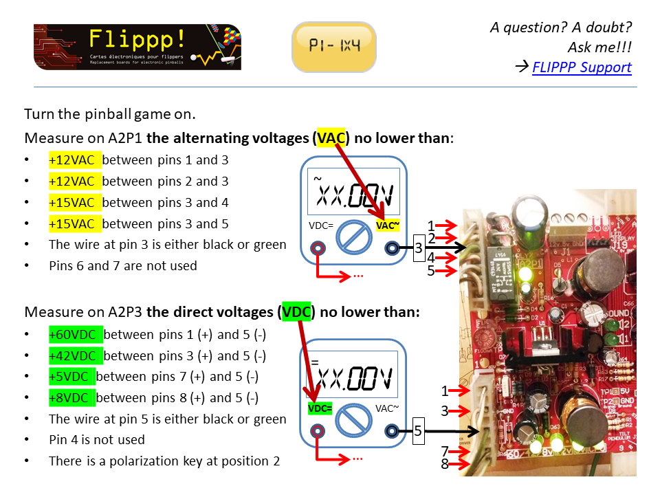
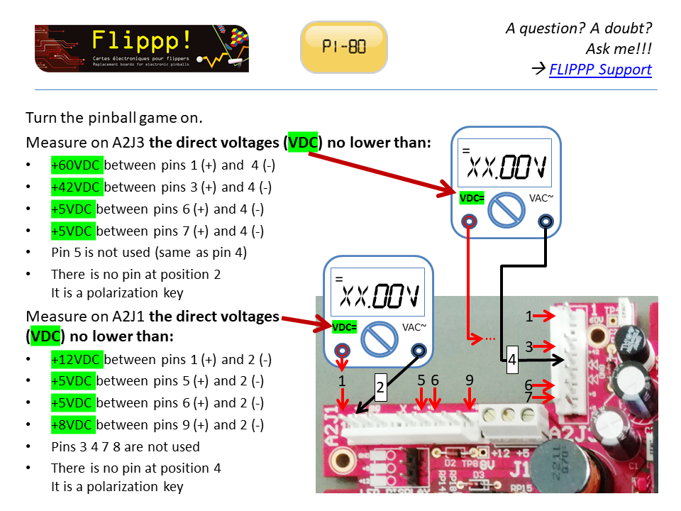
 DMM set on "VDC":
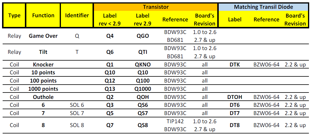
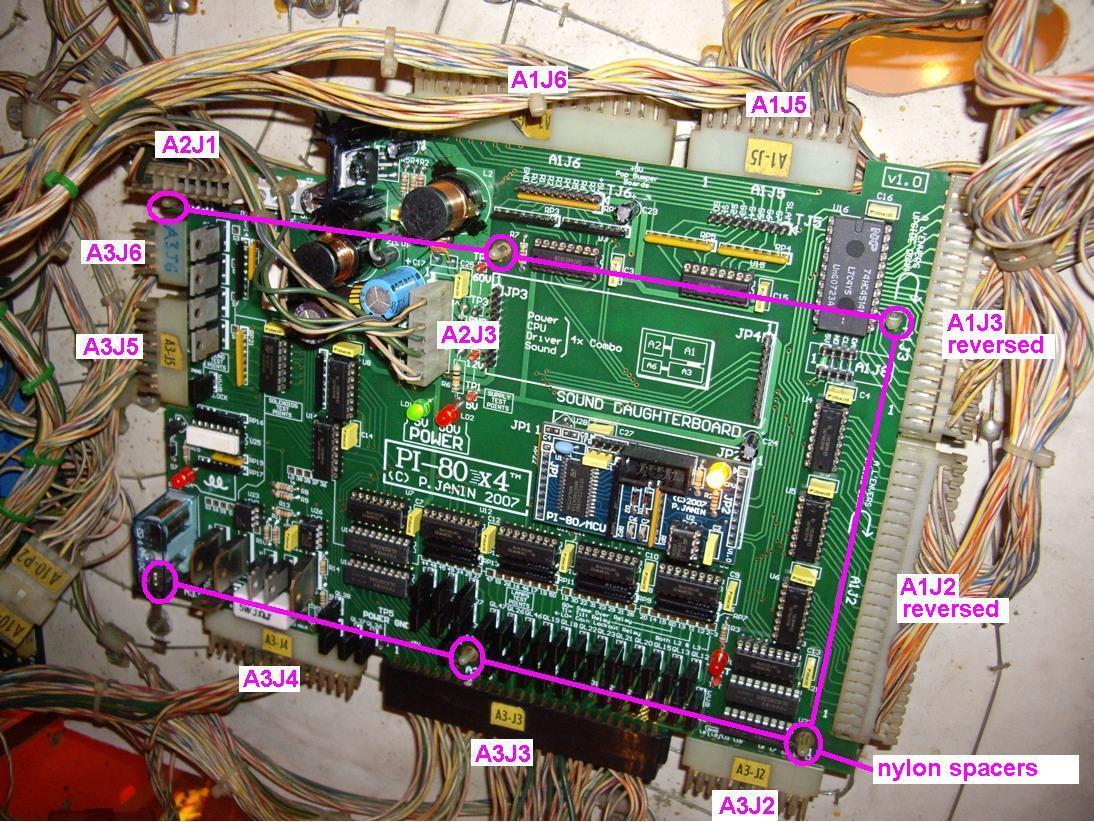
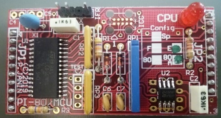
 System80 in English (E and 80 boxes ticked in the Config box)
 System80A in English (E and 80A boxes ticked in the Config box)