
 | Please note that there won't be any order shipping between July 18th and August 3rd. Next shipping on August 4th. |


TEST BENCH FOR GOTTLIEB® SYSTEM1 DRIVER
DESCRIPTION
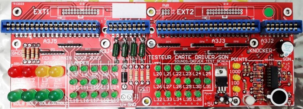
The are several areas on this test bench:- lamp outputs
- coil outputs
- sound outputs and audio amplifier
- knocker output
- 12V/5V power supply
Each LED is identified on the PCB, and labeled according to its function (lamps, coils, sound).
Specific power resistors on SOL6 SOL7 SOL8 and OUTHOLE coil outputs draw a stronger current (0.4A) than a LED to get closer to the real driving condition of a coil (5A or more). As a matter of fact, a bad transistor may seem to work under a low current (LED) but not under a high current (real coil).
The 3 sound outputs (10 points, 100 points, 1000 points) activate 3 LEDs and 3 oscillators to recreate the basic sound board used on pinballs from Cleopatra to Pinball Pool.
The knocker output activates a buzzer.
The power supply is taken from the pinball 12V, with a diode in series to prevent polarity mistakes. The +5VDC needed by the audio stage is generated via a classic 5V regulator, with a "Power +5V" indicator LED.
Compatible with all the driver boards (original Gottlieb®, Boston Pinball, Ni-Wumpf, Rottendog ...) and all-in-one PI-1/X4.
The PI-1 and PI-1/X4 boards include an additional specific test program for this bench.
INSTALLING AND CONNECTING
The test bench can either be connected on the original driver board or on the PI-1/X4 board. All the connectors are aligned, so gently push to insert: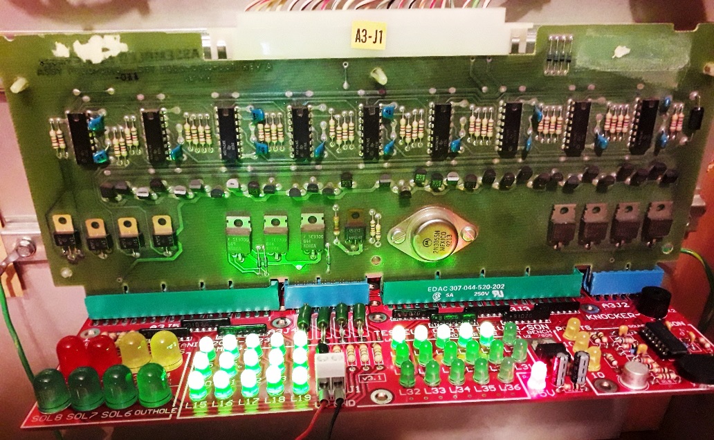
You can leave all the other connectors (A1J2 A1J3 to the displays and A1J6 A1J7 to the switches).
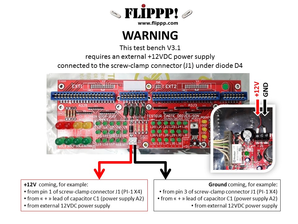
From the big C1 capacitor on the original power supply board A2
 If you're only looking for the bare PCB, choose this product:
Order or shipping quote: it's easy, add the board in the cart and let us guide you. No registration needed and no account to open!
168 € (140 € excl.tax)
 Add to cart
 160 USD
Estimated value excluding French tax. Your bank or Paypal
may apply a different exchange rate.
All payments to be made in euros (€).
 225 CAD
Estimated value excluding French tax. Your bank or Paypal
may apply a different exchange rate.
All payments to be made in euros (€).
 229 AUD
Estimated value excluding French tax. Your bank or Paypal
may apply a different exchange rate.
All payments to be made in euros (€).
 120 GBP
Estimated value excluding French tax. Your bank or Paypal
may apply a different exchange rate.
All payments to be made in euros (€).
 131 CHF
Estimated value excluding French tax. Your bank or Paypal
may apply a different exchange rate.
All payments to be made in euros (€).
Estimated value excluding French tax. Your bank or Paypal
may apply a different exchange rate.
All payments to be made in euros (€).
Estimated value excluding French tax. Your bank or Paypal
may apply a different exchange rate.
All payments to be made in euros (€).
Estimated value excluding French tax. Your bank or Paypal
may apply a different exchange rate.
All payments to be made in euros (€).
Estimated value excluding French tax. Your bank or Paypal
may apply a different exchange rate.
All payments to be made in euros (€).
Estimated value excluding French tax. Your bank or Paypal
may apply a different exchange rate.
All payments to be made in euros (€).
Related products
| show 239 € (200 € excl.tax)
|
show 42 € (35 € excl.tax)
|
 show show42 € (35 € excl.tax) 
|
 show show168 € (140 € excl.tax)
|